Lucas Frank

Engineering Portfolio

Mechanical engineer with a passion for aerospace systems and space exploration. I specialize in designing and developing mechanical solutions for challenging environments, from concept through fabrication and testing.

LinkedIn

PRIMROSE

ANSYS • Onshape • Team Leadership • Rapid Prototyping

My "flagship" project. A lunar excavation and transport rover which won 3 NASA awards.

Constant Force DTVACC Mechanism

Linkage Analysis • Onshape • CAM • Rapid Prototyping

Designed, manufactured, and implemented a passive, constant force applicator in 4 weeks. This mechanism was instrumental to AI SpaceFactory being awarded an STTR Phase 2 contract.

ESP32 RGB LED Controller

Embedded Systems • KiCad • C++ • Python • IoT

ESP32-C3 based RGB controllers for the lights in my college apartment. Working completely outside my comfort zone.

MATLAB 5 DOF Robot Arm

Onshape • MATLAB • Inverse Kinematics • Path Planning

Personal challenge: Design and simulate a 5 DOF robot arm for my robotics class in under 2 weeks.

PRIMROSE - Lunar Excavation Rover

ANSYS • Onshape • Team Leadership • Rapid Prototyping

My Role: Chassis Team Lead

Joined the Planetary Surface Technology Development Lab (PSTDL) after Level 1 design, leading the 3-person subteam through fabrication, testing, and complete redesign of a 375 kg lunar excavation rover's chassis. Responsible for integration of all structural systems into rover as well as a novel drivetrain design.

PRIMROSE Rover

Level 1 design.

Chassis Design

Level 2 design. Changes limited to enabling manufacturability.

Team Photo

Level 3 design. Complete overhaul of rover, including drivetrain.

Design Philosophy: Speed Through Simplicity

Developed a manufacturing hierarchy to maximize build speed with limited resources:

  • 3D printed if possible (brackets, spacers)
  • Bent sheet metal + rivets (no welding required)
  • Bent sheet metal + welded joints
  • Square tubing + welding
  • In-house machining utilized only when unavoidable

This approach let us build fast and iterate faster; critical when discoveries during integration demanded immediate redesigns. Even the most expensive option, making billet parts, was done in house by team members to save cost.

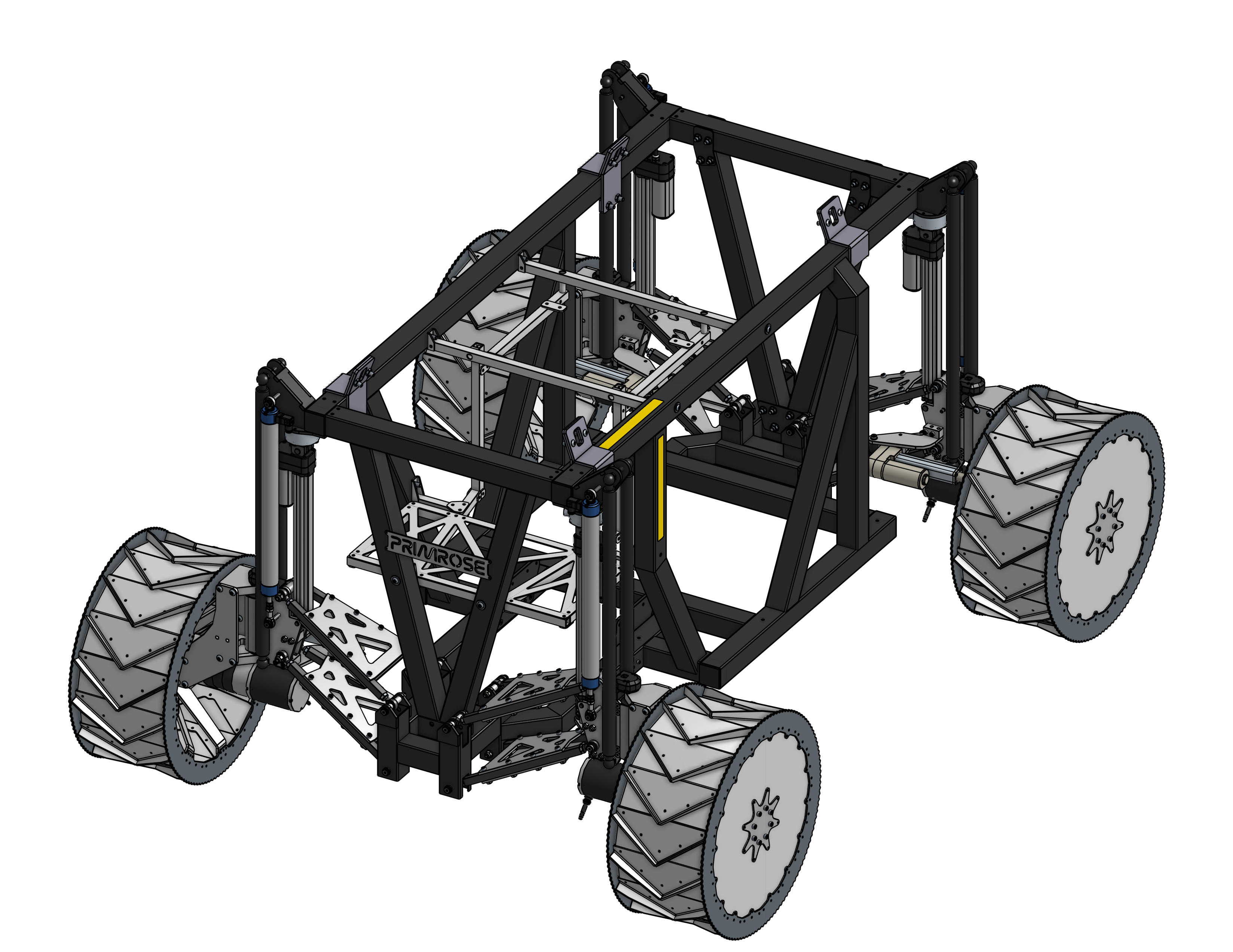
Level 2: Bringing PRIMROSE to Life

Inherited a conceptual design that needed manufacturability fixes. Key contributions:

  • Resolved geometric interferences in CAD before cutting metal
  • Designed serviceable subassemblies (learned from automotive work)
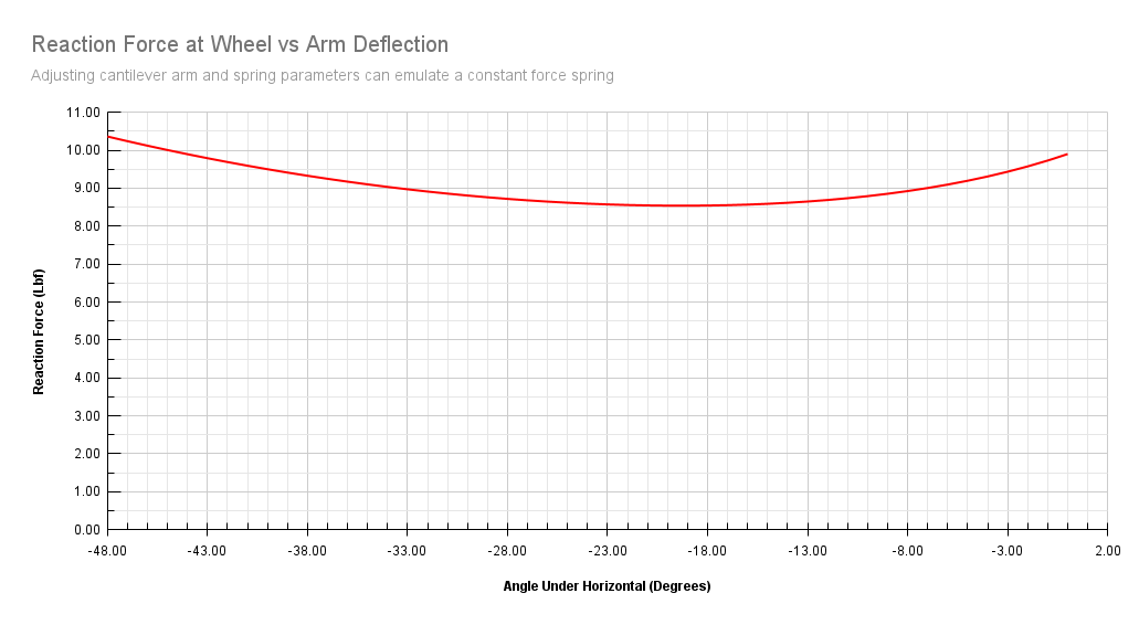
  • Modified existing suspension hardware for 15-day endurance test
  • Result: 30,063 m traversed, 2,987.2 kg excavated and dumped
Level 2 rover during endurance test

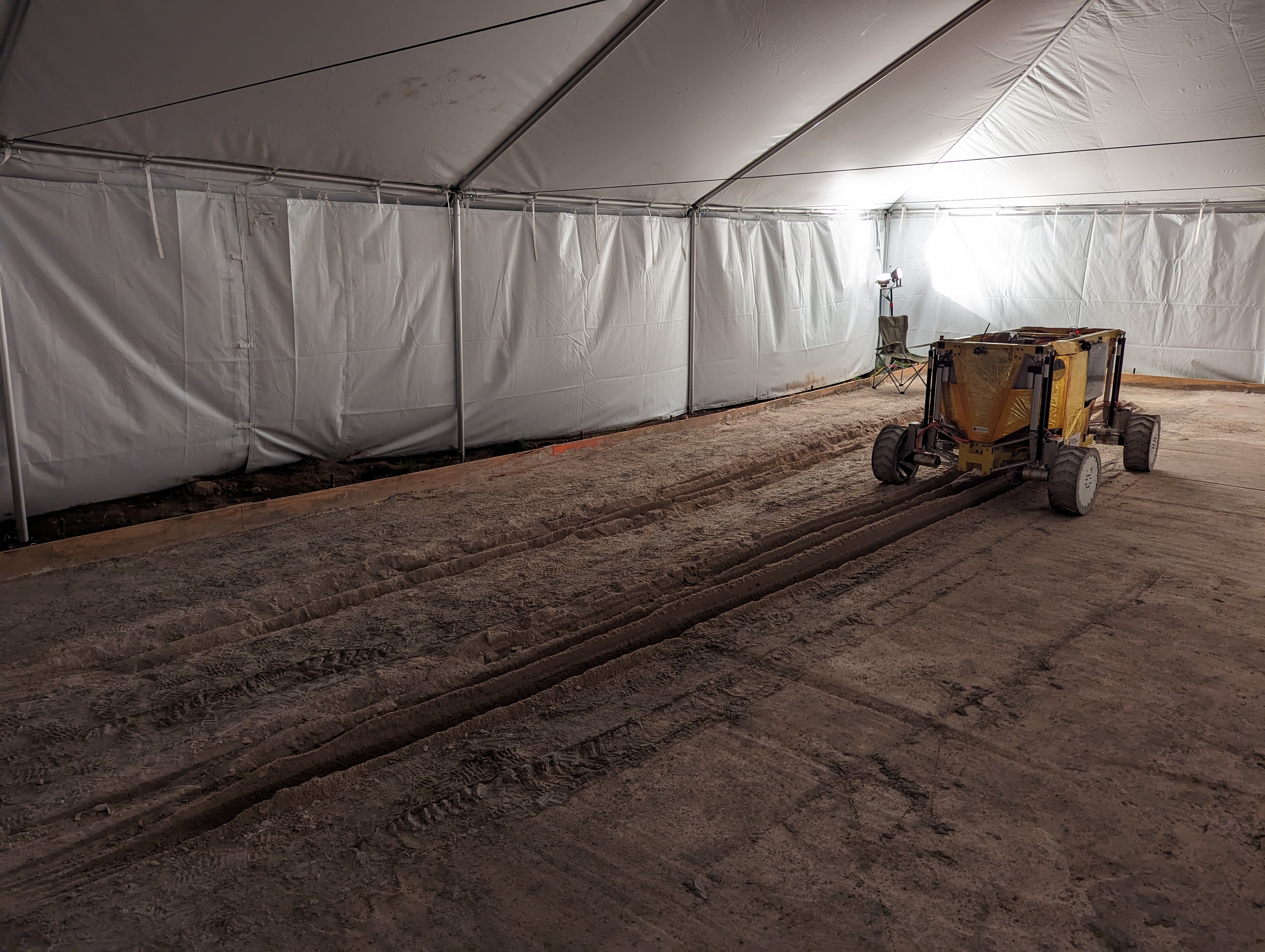
Level 2 rover during endurance test showing original configuration

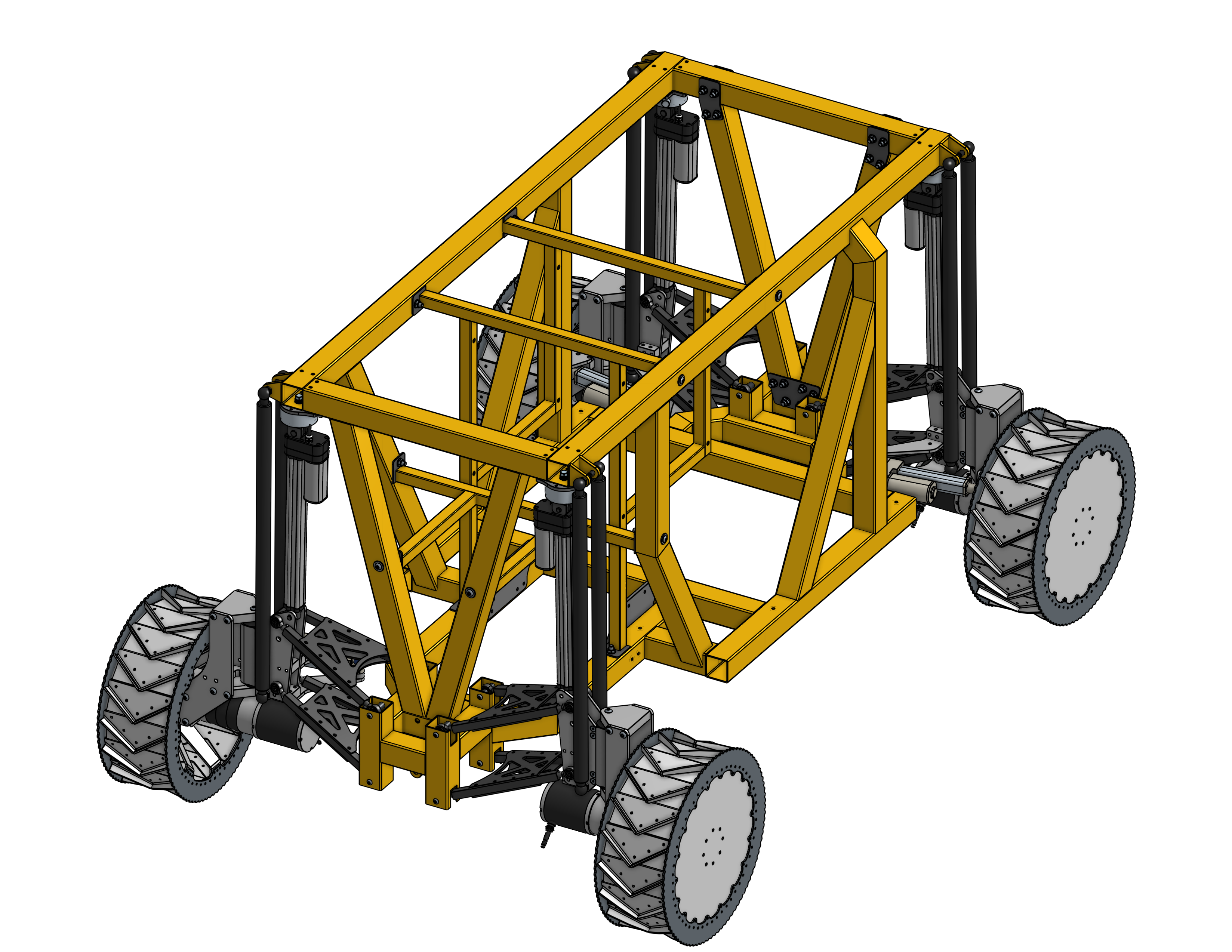
Level 3: Huntsville or Bust

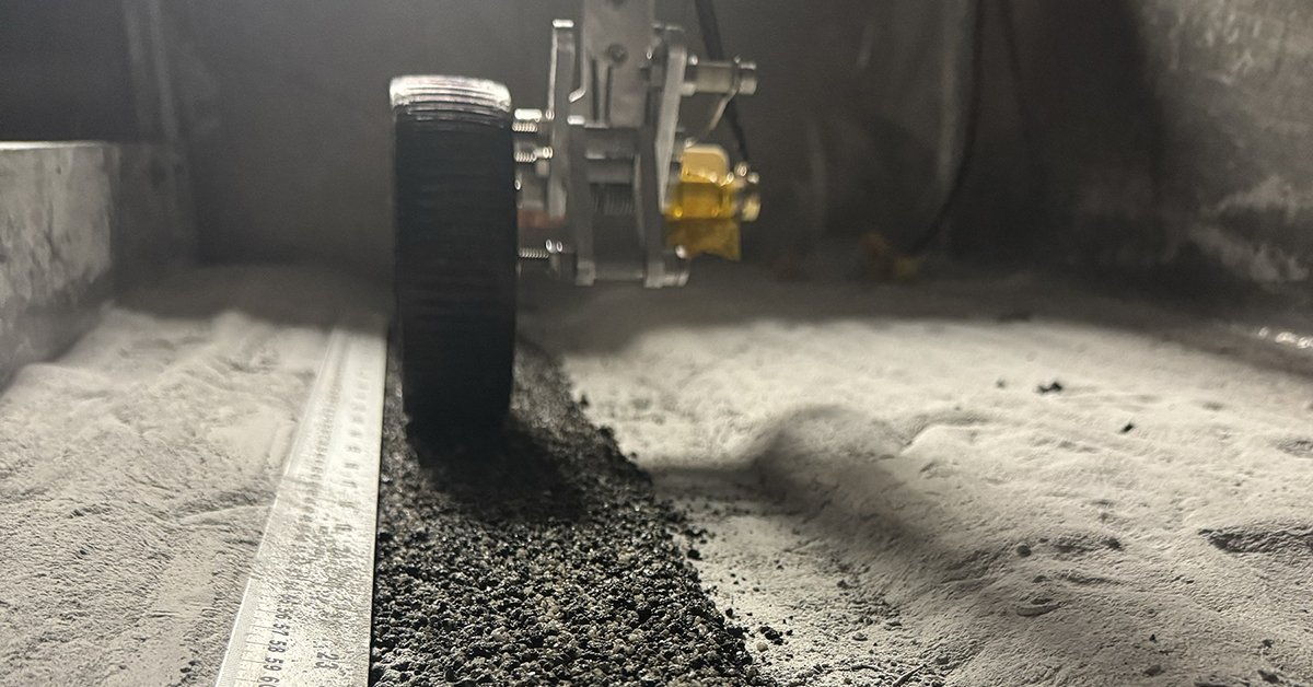
The rover was constantly down for maintenance, necessitating a rework. Worked with chief engineer and team to set new requirements, mainly: wider wheelbase for stability, larger wheels to prevent sinking in sand or regolith, 30°/30° steering capability for better maneuverability. Key contributions:

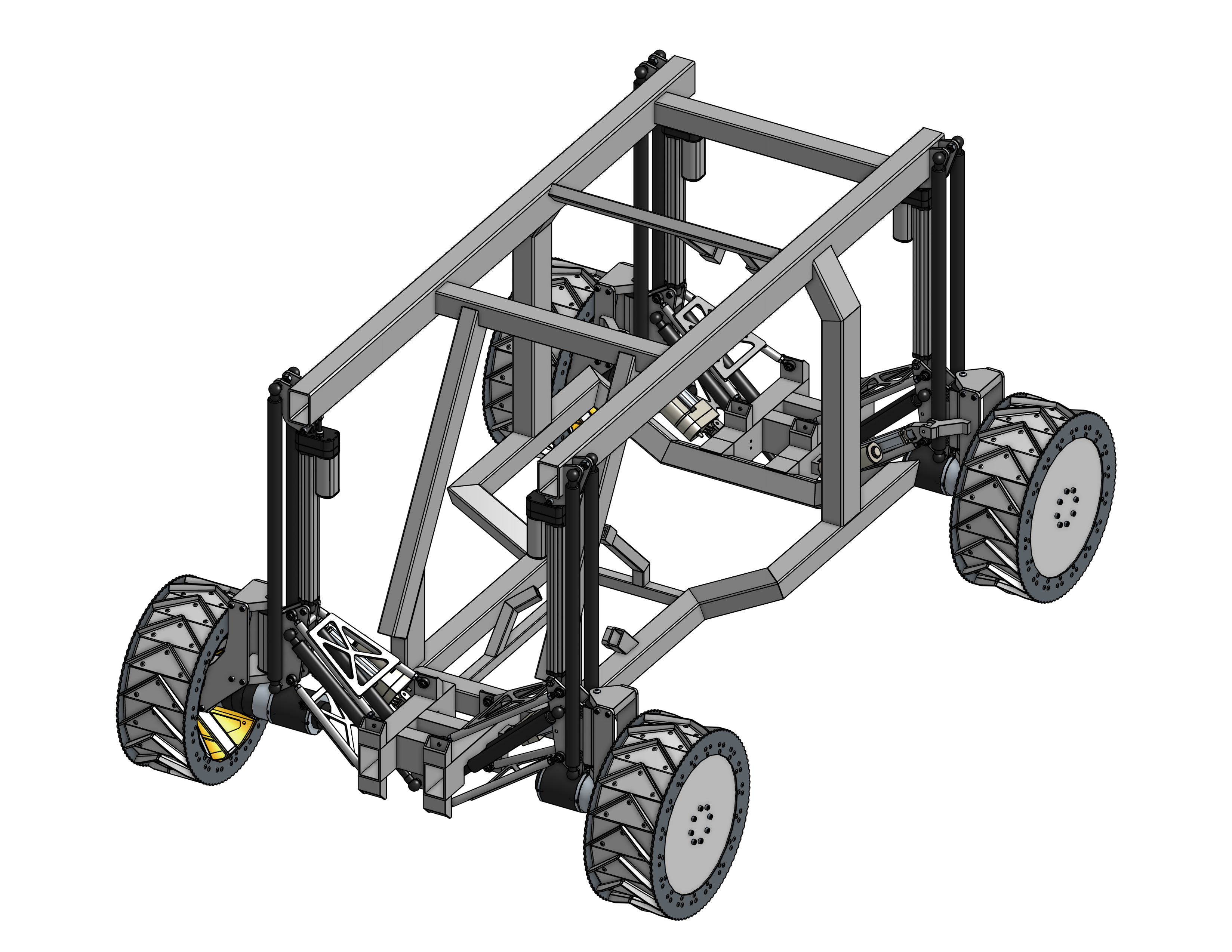
Structural Redesign:

  • Converted internal frame from steel to aluminum (weight savings + new electrical system)
  • Added frame brackets to accommodate larger wheels and wider wheelbase
  • ANSYS FEA with aggressive FoS (verified against hand calcs)
  • Maintained top-down CAD architecture in Onshape, enabling fast design changes
GIF showing ANSYS analysis

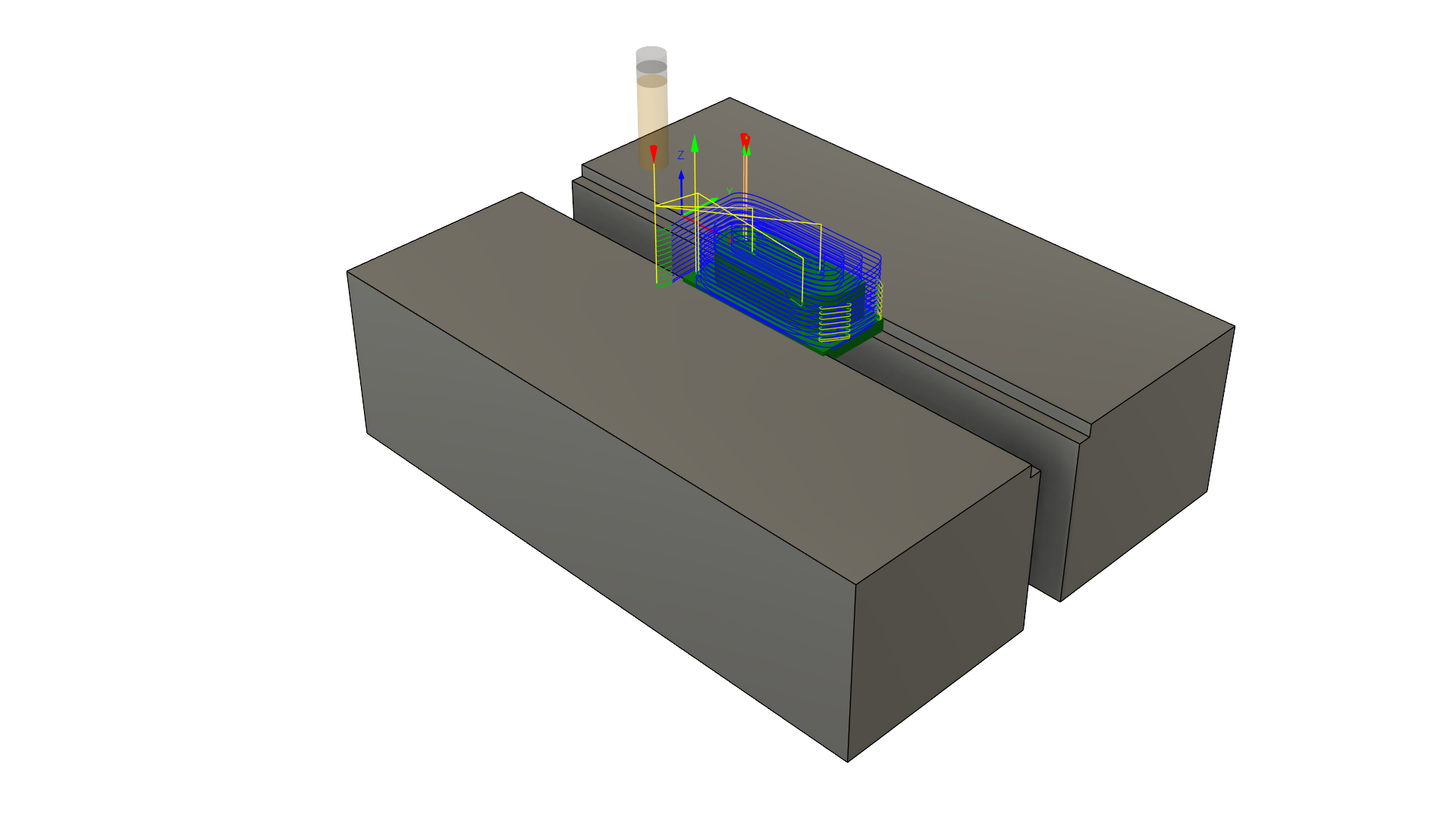
ANSYS quasi-static analysis with frame constrained by free sliding wheels

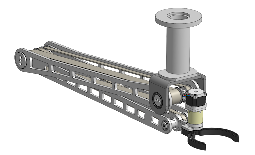
Suspension Overhaul:

  • Adapted existing kinematic layout geometry to new wheel envelope
  • Redesigned A-arm mounts and most suspension components
  • Modified frame to support extended wheelbase and larger wheels
  • Implemented 30°/30° steering angle
New suspension assembly

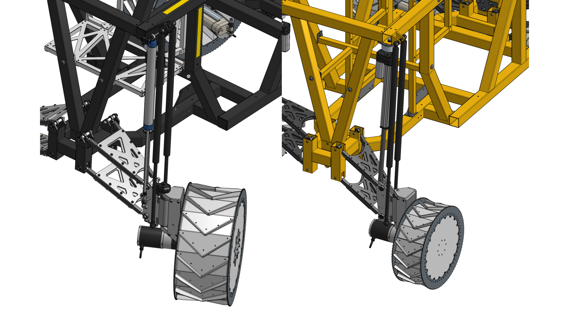
Level 3 (left) vs Level 2 (right) suspension assembly

Integration Under Fire

Fast design meant some components were modeled just days before fabrication. This required:

  • Constant communication with excavation/electrical teams
  • On-the-fly modifications when reality didn't match CAD
  • Balancing "perfect" vs "good enough" to meet deadlines

The payoff: 85% excavation rate improvement enabled by a chassis that could handle the increased loads, and 100% drivetrain reliability.

Final Results & Reflection

The rover secured 3rd place overall at NASA's Break the Ice Lunar Challenge, validating our scrappy approach against teams with significant industry backing. More importantly, this project transformed my engineering practice. The PSTDL gave me the freedom to fail fast and get hands on. Working alongside a team that trusted an undergrad to work as an engineer, designing and redesigning critical systems, taught me that good engineering isn't about perfection; it's about making the right compromises under pressure.

Team after successful competition performance

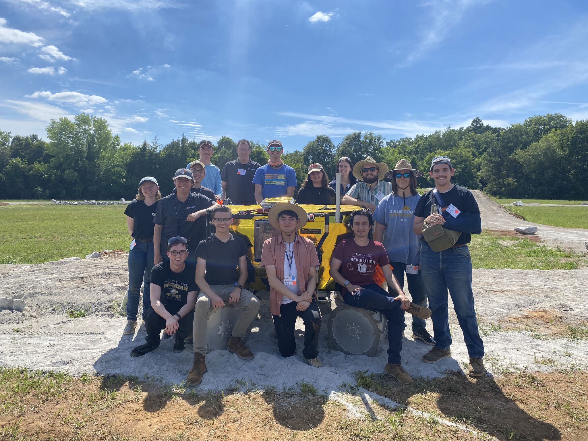
Team photo after successful competition

NASA Video

I cannot thank the PSTDL enough for the opportunity to be on such an amazing team.

Links

PSTDLNASA's Break the Ice

Constant Force DTVACC Mechanism

Linkage Analysis • Onshape • CAM • Rapid Prototyping

The Challenge: 4 Weeks to Enable Critical Testing

Fresh off our success at NASA's Break the Ice Challenge, the deadline to test for one client, AI SpaceFactory, was rapidly approaching. We had to design and build a mechanism to apply 10 lbs of constant force to their lunar road-paving technology for testing in the Planetary Surface Technology Development Lab (PSTDL) Dusty Thermal Vacuum Chamber (DTVACC). We had just over 4 weeks before their scheduled test date.

While the rest of the small team worked to get our regolith bed gantry motorized, I was assigned as the sole engineer on the constant force mechanism. I was responsible for concept development through final integration. The mechanism needed to maintain a constant force across 5 inches of vertical travel to accommodate road surface variations while surviving vacuum conditions.

Constant force mechanism CAD model

Final mechanism design showing lever arm and wheel assembly

The Solution: Maximize Simplicity

Rather than complex active control systems, I developed a purely passive mechanism that exploited two competing non-linear effects:

  • Variable radius cam effect: As the wheel displaces vertically, the perpendicular distance from the spring's line of action to the pivot varies non-linearly
  • Toggle mechanism principle: Approaching kinematic singularity near 180° transmission angle creates exponentially increasing mechanical advantage
Wheel force for a given deflection angle

Spreadsheet plot of wheel force over angle range

By carefully tuning the torsion spring selection and lever arm geometry, these effects cancelled out to produce near-constant force (±1 lb) across the entire travel range. Spreadsheet analysis proved the concept before moving to CAD.

Rapid Development Timeline

  • Week 1: Mathematical proof of concept and spring selection
  • Week 2: Parametric CAD development and sheet metal orders
  • Weeks 3-4: In-house CNC machining of precision bearing blocks, assembly, and integration

The parametric, top-down CAD approach proved critical when last-minute changes were needed. Our sheet metal supplier rejected my initial files, requiring a redesign of several parts; however, because the design was fully top-down, the fix took less than an hour and the assembly updated automatically. Every component was designed for rapid fabrication: sheet metal where possible, 3D printing for non-critical parts, and machining only when necessary meant only 3 parts needed to be made in house.

CAM for bearing mounts

CAM toolpath for bearing mounts

Results & Lessons Learned

The mechanism functioned well during testing, enabling AI SpaceFactory to validate their paved lunar road under realistic loading conditions. The successful test was instrumental in securing their STTR Phase 2 contract.

Mechanism during DTVACC testing

Mechanism undergoing testing in the DTVACC

This project taught me valuable lessons about managing aggressive timelines and client expectations. While we delivered a working solution, the 12-hour days and extreme time pressure highlighted the importance of realistic project scoping. Working under tight constraints can give way to creative solutions, but also creates an environment for failure.

Technical Takeaway

Good engineering under pressure isn't about perfection; it's about finding elegant solutions that work within constraints. By leveraging fundamental mechanical principles instead of active control systems, we delivered a robust mechanism that met all requirements under an extremely tight deadline.

Links

PSTDL DTVACCAI SpaceFactory

ESP32 RGB LED Controller

Embedded Systems • KiCad • C++ • Python • IoT

Overview

Coming from mechanical engineering with zero embedded experience, I wanted complete control over the RGB lighting in my college apartment. Rather than buying off-the-shelf controllers, I decided to build my own ESP32-based system from scratch. These controllers can talk to everything from my Apple Watch to my Arch server through simple HTTP requests.

The goal was ambitious: design custom PCBs, write firmware with smooth animations, and deploy controllers to every room. This project forced me completely outside my comfort zone, but gave me hands-on experience with full ownership of both hardware and software.

Custom PCB with ESP32-C3

Final SMD PCB design with ESP32-C3 and MOSFET drivers

Hardware

Started with through-hole components on perfboard to prove the concept. I selected MOSFETs from Digikey using a simple method; I set my power supply to 24V (matching the LED strips), measured current draw from the power supply, and chose components with appropriate voltage/current ratings. I had several Seeed XIAO ESP32-C3's leftover from a simpler project, and implemented one in the prototype.

After validating the circuit, I transitioned to SMD PCBs to reduce costs and gain experience. Playing around with my ancient oscilloscope, I found the flat Miller region on the rising edge of my MOSFETs. After further research, (and learning what the hell the Miller region was), I decided to implement gate drivers to mitigate switching inefficiencies. Assembly was done with a hot air gun and patience, no reflow oven needed for small quantities.

PCB Gerber File

PCB Gerber file

Software

I built a real-time animation system around HTTP endpoints that could queue color transitions with custom timing curves. The core innovation was using a single mathematical function (found on Stack Overflow, of course) that allowed for varying a single alpha parameter to create different smoothing curves and wave shapes:

  • α = 1: Linear interpolation (sawtooth waves)
  • α = 2-10: Smooth easing functions (sine-like waves)
  • α > 10: Step transitions (square waves)
Simplified program flowchart

Basic program flow

Debugging Boot Issues

The controllers frequently got stuck in loops as I learned the basics of C++, making re-flashing difficult. Through debugging, I discovered I'd connected some traces to GPIO pins that also served as boot configuration pins. When these pins were pulled high or low by my circuit, the ESP32 would enter different boot modes, making flashing difficult. While the boards functioned when flashed, this was a major roadblock for some time.

Problems like this served as reminders as to how much I have to learn with embedded systems. Little issues like that are learned practically and only through experience.

Distributed Control & Synchronization

Each controller operated independently with its own web server, but synchronization across rooms was achieved through timed HTTP requests. Since everything ran on the local network, latency was minimal and coordination worked reliably. This architecture allowed control from Python scripts, iOS shortcuts, direct curl commands, any device that could send HTTP requests. Most of the animation was done with Python scripts I wrote for my Arch Linux server. I also implemented some automation, using a shortcut on iOS to call the server to turn on the lights when I turned off my alarm.

Technical Lessons Learned

This project helped me understand that embedded development is about working with constraints. Memory fragmentation concerns led me to avoid complex data structures, which pushed me toward simpler solutions using structs and arrays rather than classes and queues. The controllers stayed on for months without a single crash or noticeable bug!

As someone coming from mechanical engineering, tackling embedded systems required starting with basic prototypes and gradually building complexity; starting with through-hole prototypes, onto PCB design, SMD assembly, and fumbling around in C++ until I got something useful. It was an incredibly fulfilling project.

First controllers immediately after soldering

The first two controllers after completion

Results

Successfully deployed controllers to every room in the apartment, each running stable firmware with smooth color transitions. The system ran for months without any downtime and I only had one failed controller.

Links

GitHub Repository

MATLAB 5 DOF Robot Arm

Onshape • MATLAB • Inverse Kinematics • Path Planning

Overview

I took a robotics and mechatronics class at my school, which provided the opportunity for extra credit: design and present a robotics project of any kind. So long as it pertained to the class in some way, it was fair game. It was extremely open ended, so I took it as a challenge to design a robot arm to manipulate a coffee mug on my desk. From this idea I worked out some requirements.

Requirements

  • Ability to lift and manipulate a full coffee mug with a weight of 5.5 N
  • Move objects over the full 3 foot range of my desk
  • Driven with stepper motors
  • At least 5 degrees of freedom including the end effector
Hand calculations

The quick hand calcs done to spec the motors

Robot Arm CAD

The detailed CAD model of the robot arm.

After the detailed design of the arm was completed, I made a model with simplified geometry to make a URDF model. This was done easily using onshape-robotics-toolkit. For simulation, I went with the MATLAB robotics toolbox. I had used ROS for previous projects, and wanted to try something different.

As I only had a few weeks to work on the whole project, the simulation ended up being very simple; inverse kinematics are solved to put the end effector in preset points, the motion planning then just interpolates the joints to move from one position to the other. So the target points are solved for in task space but movement is done in joint space.

Animation from simulation

During the live demo I did for the class, someone asked me to make the robot pour the mug on my lap

Results

Gained experience working with MATLAB robotics toolbox, and applied most of what I learned in the class. Received full extra credit!

Links

Onshape robotics toolkit